.png?crc=4243365975)
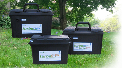
SUSTAINABLE IRRIGATION AND LANDSCAPE LIGHTING SOLUTIONS
SUPPORT
Set up & Installation
Installing the battery
To install the battery in a Turbo Rain / Glow
System, complete the following steps.
1. Place the carrying case in front of you, with the latch
positioned to the left. Open the case by releasing the
toggle latch as shown in Fig. 1.
2. Unhook the Velcro safety strap, and expose the 4
battery alignment bolts as show in Fig. 2.
3. Place the battery, part #3, within the 4 locating bolts, making
sure that the black terminal is on left side and red
terminal is on right side. Place the narrow end of
safety strap through the slot on the wider end. Pull
tightly on both ends and secure as shown in Fig. 3.
4. Connect the wire leads to the battery. Connect black
wire to black terminal (neg) and red wire to red
terminal (pos) and tighten connections with screw
driver and small pliers. It is important that the
connections are tight as shown in Fig. 4.
The battery is now installed properly.
.
Fig. 1
Fig. 2
Fig. 3
Fig. 4
Installing the Water Output line
1. To install using the quick connect components, select the components as
shown in Fig 1.2. First, thread the output side QC fitting, part #1, on to the male threads on the
Turbo Rain case identified as Water Output. Then, thread the QC
fitting for irrigation, part #12, into a Female DL fitting, part #8. Next,
insert .700 tubing into other end of Female DL fitting and spin down lockingnut for water tight connection. Complete assembly is show in Fig. 2.
3. To easily engage / disengage water output line, insert part #12 into part #1 and
push until you hear audible clicking sound. To remove, slide back sleeve on
part #1 toward Turbo Rain case while at the same time pulling back on water
line.4. If you want a more permanent water output connection, thread the
part #8 directly on to the water output male threads that protrude from the
Turbo Rain case. Make sure the plastic washer is inside the part #8 for a
water tight seal. For this installation you do not use the QC fittings. Refer to
Fig 3.Fig. 1
Fig. 2
Fig. 3
Connecting the Solar Panel
1. The Turbo Rain system is supplied with a 20-watt solar panel with a 10-foot power
cord.2. The gray connector on Turbo Rain will properly mate with the gray connector on
the solar panel power cord.3. Just align the 2 connectors with both red marks facing each other, and squeeze
the 2 connectors together for a perfect electrical connection. See Fig. 1 & Fig. 2.4. The standard Turbo Rain system has a 3-amp charge controller. You can connect
2 – 20 watt solar panels together and still be under the 3-amp capacity of the
charge controller.5. For best solar panel results, face the solar panel to the south. If you cannot point
south, face to the east for morning sun or west for late afternoon sun.Fig. 1
Fig. 2
Connecting to the Top of a Rain Barrel or Tank
Fig. 8
Fig. 7
Fig. 1
Fig. 2
Fig. 3
Fig. 4
Fig. 5
Fig. 6
1. Locate a safe, level surface area that will be accessible to the operator. Be aware that all
water input connections must be secure and air tight for the pump to operate at maximum
efficiency.2. From the parts supplied, locate input side DL & QC fitting, part #2. (Fig. 1)
3. Insert the tubing on Turbo Rain identified as “Water Input” all the way on to part #2 and
secure nut on to tubing to create an air tight connection. Make sure the QC fitting is tight and
that you can visibly see the small “O” ring on QC fitting. (Fig.2)4. Locate Filter Assembly with DL Fitting, part #6 as well as PVC Elbow with QC fitting, part #7.
(Fig 3.)5. The DL fitting comes pre-installed on the filter. To install Elbow section, apply liberal amount of
Teflon tape, part #13, to filter threads on top of filter and rotate part #4 clockwise until
tight. Position QC fitting on Elbow away from filter for easy connection to Turbo Rain. Angle of
filter must be positioned as shown for filter to operate properly. When you connect the 2 QC
connections together, you will hear an audible “click” indicating proper connection. (Fig. 4)6. Position Turbo rain on top of tank (see step 1) with filter assembly attached. This will assist
you in locating where to mark the ¾” hole needed for the suction tubing to be installed. (Fig.5)7. If tank is deeper than 24”, couple both pick up tubes provided using the Straight Barb Fitting,
part #9. Install the “T” barb to the bottom section of tubing later, using the main access cutout
in tank.8. Install tubing through ¾” hole, and attach T Barb Fitting, part # 10, to bottom of tube. Lower to
bottom of tank. Mark exposed tubing at top of tank noting height level with bottom of DLFitting on Filter Assembly. Then, measure up and mark an additional ¼ inch. Cut tubing at
this final mark. Install top tubing end into DL Fitting and push all the way in. Secure nut on DL
Fitting for air tight connection. The “T” fitting will now sit approximately 1” off the bottom of the
tank. (Fig. 7 & 8).Note: Maintain secure connections and level connection from Turbo Rain to filter assembly for maximum efficiency.
Drill 3/4" hole -------
Connecting to the Bottom of the Tank
1. You may choose to hook the Turbo Rain system to a connection at the bottom of the tank
rather than mount it on top of the tank.2. Because the diaphragm pump is a “flow thru” pump, this means there is nothing inside the
pump to stop the water flow out of the tank after irrigation. In other words, you very likely will
empty the tank of water although you do not intend to do so.3. One remedy would be to insert a manual on / off valve to stop the flow of water when finished
watering. This is not ideal if you have an automatic model which will cycle on and off when
you are not present to manually move the on / off valve.4. We recommend that you use a battery operated “Hose Spigot Timer”. This can be placed
either between the tank and the Turbo rain, or between the Turbo rain and the irrigation.5. We recommend placing the “Hose Spigot Timer” between the water output of Turbo Rain and
the irrigation. Fig. 16. See section on multi – zone watering for more information.
Connecting to a Lake or a Pond
Fig. 4
Fig. 5
Fig. 1
Fig. 2
Fig. 3
Fig. 6
1. The connectors included with the Turbo rain shipment will easily work with ½”
plastic irrigation tubing.2. Position the Turbo Rain unit as close to the water source as possible.
3. Working backwards from the Turbo Rain unit to the water source, first insert the
Input Side DL & QC fitting, part # 2, into the tubing that extends out from the case
marked “Water Input”. Then unscrew the QC fitting to expose the threads on the
DL fitting. (Fig 1.)4. Using the parts shipped with Turbo Rain, screw a female DL fitting, part # 8, on to
the exposed threads on the male DL fitting now protruding from the “Water Input”
tubing. (Fig 2.)5. Next, determine how long the tubing will be between the Turbo Rain unit and the
filter. Cut the necessary length of tubing and insert one end into part # 8. (Fig 3.)6. Next, thread part # 8 on to the filter (one is already installed on the
other end) using Teflon tape, part # 13, for airtight connection. (Fig 4.)7. Filter must be pointed in the proper direction to work. (Fig 5.)
8. Finally, connect tubing to part # 8 on the end of the filter and direct
the tubing into the pond or lake. (Fig 6.)Connecting a Float Switch
1. A marine style float switch is sold as optional equipment with the
Turbo Rain automatic system only.
2. This float switch should be mounted to a piece of aluminum or other
solid material to keep the float switch secured to the bottom of the
tank.
3. The float switch is supplied with an 8 foot cord with an accessory port
connection installed.
4. Locate the accessory port connection located on the Turbo Rain case,
which is located on the same side as the water input. It is clearly
marked. Note: Accessory port connection will accept a float switch
or a rain / freeze sensor. Fig. 1
5. Insert the male connector into the accessory port connection, and push in firmly.
Fig. 26. The float switch will now control the operation of the pump based
upon the on / off programming of the auto timer. If the auto timer
calls for the pump to operate, and there is insufficient water in the
tank, the float switch will prohibit pump operation. With sufficient
water in the tank the pump will operate normally.
7. Only 1 accessory port connection is supplied with Turbo Rain,
however, dual accessory ports can be supplied to run both a float
switch and a rain / freeze sensor as an available option.
Fig. 1
Fig. 2
Connecting a Rain/Freeze Sensor
1. A rain / freeze sensor is sold as optional equipment with the
Turbo Rain automatic system only.
2. This rain / freeze sensor includes all the mounting hardware for mounting on a
rain gutter or on a solid surface.3. The rain / freeze sensor is supplied with a 25 foot cord with an accessory port
connection installed.4. Locate the accessory port connection located on the Turbo Rain case,
which is located on the same side as the water input. It is clearly
marked. Note: Accessory port connection will accept a float switch
or a rain / freeze sensor. Fig. 1
5. Insert the male connector into the accessory port connection, and push in firmly.
Fig. 26. The rain / freeze sensor will now control the operation of the pump based upon
the on / off programming of the auto timer. If the auto timer calls for the pump to
operate, and it has rained recently (or near freezing), the rain / freeze sensor will
prohibit pump operation. If it has not rained recently or it is not near freezing, the
pump will operate normally.7. Follow directions that are included with rain / freeze sensor to set the sensitivity of
the rain sensor.8. Only 1 accessory port connection is supplied with Turbo Rain,
however, dual accessory ports can be supplied to run both a float
switch and a rain / freeze sensor as an available option.
Fig. 1
Fig. 2
Installing a Pump Pressure Bi-Pass
If you have too few drippers on your irrigation line and your pump cycles on and off frequently, it is best to add a pump pressure by-pass to allow the pump to operate at the proper level of power (amps) and to reduce wear and tear on the pump.
1: As close to the tank as practical, cut the irrigation line and insert a “T” fitting, (Fig. 2).
2: At the “T”, insert short section of irrigation tubing and then insert a manually adjusted water shut off valve, (Fig. 3).
3: Attach irrigation tubing to the other end of the water shut off valve and extend this tubing all the way back to the top of the water tank, (Fig. 4).
4: Fine tune the water flow for irrigation. Start by opening up the manual water valve to allow full water flow back to the tank.
5. Start up Turbo Rain pump and slowly close the manual water shut off valve until you achieve the optimum flow of water at your drip system and the pump runs smoothly at the least amount of power consumption (amps). Any water that is by-passed away from the drip system is sent back to the water tank, so that no water is lost.
Fig. 1
Fig. 2
Fig. 3
Fig. 4
How to Disconnect / Connect Wires From Grey Connectors
The gray connectors on the Turbo Rain system are intentionally different so that cross connections cannot be made. On the Turborain case you will find a solar panel connection and an electrical charge connection. Each gray connector has a red mark to identify the positive side to / from the battery. When you receive the solar panel it will have a gray connector installed that will only mate with the gray connector on the Turbo Rain case. If you order an electric battery trickle charger, it too will have a special gray connector that only mates to the gray connector on the electrical charge port of Turborain.
To connect new wires to the gray connector:
1. Strip wires back 1/4" and twist them clockwise to a tight strand, (Fig. 1).
2. Locate the small white plug tool included in your parts kit, (Fig. 2).
3. Insert the plug tool into the gray connector as shown in Fig. 3.
3: Push down on the lever, and insert wire, (Fig. 4).
4: Release lever and remove, (Fig. 5)
To remove a wire from the gray connector, repeat steps 2-4.
Fig. 1
Fig. 2
Fig. 3
Fig. 4
Fig. 5
How to Check and Replace the 10 Amp Fuse.
The Turbo Rain system has a fuse protected circuit for safety. Power from the battery to the pump and power to the battery (from solar panel and electrical trickle charger) all pass through the fuse protection. If you can not activate the pump, have a low battery or can not see the red light on charge controller for solar panel power, you might have a burned out fuse.
1. Unscrew the fuse cap by turning counter clockwise, (Fig. 1). One end of the fuse will be secured in the removable cap.
2. Examine fuse filament to see if it is a solid wire or “melted” wire, (Fig. 2)
3. Remove “melted filament” fuse and replace with new like kind 10 amp fuse,
(Fig. 3)
4. Reinsert cap on fuse body and screw clockwise to secure, (Fig. 1).
Fig. 1
Fig. 2
Fig. 3
Extending the Wires From a Solar Panel
Fig. 4
Fig. 7
Fig. 10
Fig. 5
Fig. 8
Fig. 11
Fig. 1
Fig. 2
Fig. 3
Fig. 6
Fig. 9
If you would like to change out the solar panel wire or extend the wire without cutting the wire and splicing the wires together, this is very easy to do.
1. First, turn solar panel to expose back of panel. Locate electrical junction box.
(Fig. 1)2. Slide cover down and remove. (Fig. 2)
3. Remove wire hold down tab and set aside. (Fig. 3)
4. Remove screws that hold down metal tab that keeps wire leads secured. (Fig. 4)
5. Pull out old wires and gently lift both tabs to accept new wire leads.
(Fig. 5)
6. Insert new stripped wires, noting + sign is for positive or red wires and – is for
negative or black wires. Insert wires under metal tab, and insert screw and
secure. (Fig. 6 & 7)7. Position wires as shown, make sure the wires extend out through the channel
provided. (Fig. 8)8. Reinstall wire hold down tab, and secure with screws. (Fig. 9)
9. Replace cover and secure. (Fig. 10)
10. Replace gray connector noting polarity. (Fig.11)
Extending the Wires From a Solar Panel, Float Switch or Rain/Freeze Sensor
1. Keeping the wire end with the gray connector or the accessory port connector, measure back about 1' from the connector to determine where you want to make the splice.
2. You will need to strip wires back 1/4" on the both ends of the of your original lead and on both ends of the splice wire, (Fig. 1).
3. Using # _ standard butt connectors, insert wires and crimp securely for best
results, (Fig. 2). Polarity (red + / black -) is most important for solar panel. For a float switch or a rain / freeze sensor, polarity is not important.
Add electrical tape to keep moisture out, (Fig. 3) When finished, solar panel must have original gray connection inserted at end, and the float switch and rain / freeze sensor must have accessory port connections secured.
Fig. 1
Fig. 2
Fig. 3
Installing a Vacuum Breaker
With the Turbo Rain system mounted at the top of the tank, it is sometimes
necessary to install a vacuum breaker to interrupt the flow of water to the
garden from the tank so that all of the water stored in the tank does not siphon
out and leave the tank empty.1. Garden Green EcoSolutions, LLC inventories vacuum breakers for immediate
shipment. (Fig. 1)2. Installation is easy. First remove the “Output Side QC Fitting, part # 1. (Fig 2.)
3. Then thread the vacuum breaker female threads directly on the male threads
of the water output fitting protruding from the Turbo Rain case. Note: Vacuum
breaker has rubber washer for proper seal. (Fig 3.)4. Then thread part # 1 directly onto the male threads from the end of the vacuum
breaker. (Fig 4.)Fig. 1
Fig. 2
Fig. 3
Fig. 4
Multi-Zone Irrigation
1. It is possible to automate multi – zone irrigation by adding a “hose spigot timer” with enough zones to
satisfy the requirements.2. Select a “hose spigot timer” with enough programmable zones and attach between the Turbo Rain
automatic system and the irrigation lines. Fig. 13. Once you have connected the water lines, just sync the different zone start and finish times with the
Turbo Rain automatic timer.4. Keep in mind that to run multi – zones, you may need additional solar panel power and you also may
need zone specific pump pressure by pass valves.Checking Amp Draw on the Pump Motor
1. To better understand your Turbo Rain solar powered rain water irrigation system, it is good to
know how many amps your pump consumes on a per hour basis.2. Your battery, when fully charged, holds approximately 18 amp hours of “power” measured at
12 volts.
3. A general tip to setting up the Turbo Rain system is to set up water pumping with the least
amount of burden on the pump, which means the least amount of amp draw. Your pump
should run between 4 to 9 amps per hour. Once it reaches 10 amps it will blow the fuse.4. Refer to section on Pump Pressure By – Pass to fine tune your pump burden, or amp draw to a
minimum.5. Measuring amp draw is easy. First you need a good amp / voltage meter for DC measurement.
See Fig 1.6. Set meter to read DC amps.
7. Start irrigation system and allow to run for a minute or so. Fine the positive (red) lead from
the pump and disconnect from female bullet connector. Fig 2.8. Using the leads from the electrical meter, hold one lead (black) on to the red wire with male
bullet from the pump, and the other lead (black) on to the metal part of the female bullet
attached to the same red wire leading to Turbo rain electrical system. This will complete thecircuit and pump will start running. Read DC amps after the system has stabilized. Fig. 3.
9. If you read 5 amps on the meter, and you run the system for 30 minutes each day, you
consume approximately 2.5 amps each day of usage.10. You should now compare this amp usage against what your solar panel is capable of
providing back to the battery on a full sun charge as well as a cloudy day charge.
Fig. 1
Fig. 2
Fig. 3
Checking Solar Panel AMP Output
1. To better understand your Turbo Rain solar powered rain water irrigation system, it is good to
know how many amps are expected to be generated from your solar panel back to the battery
on a sunny and cloudy day.2. You should also understand how many amps your Turbo Rain pump will consume from the
battery on an average irrigation day.3. First locate the electrical meter that is set for DC Amps. This is the same meter used for
checking the amp draw on the motor, as well as checking the condition of your battery after
re-charging either with solar panel or electrical trickle charger.4. Locate the solar panel connection where the solar panel connects to the Turbo rain system.
(Fig. 1)5. Disconnect the 2 connectors. (Fig. 2)
6. Using the electrical meter set on DC Amps, insert the meter probes into the gray electrical
connector as show. (Fig. 3)7. Depending upon sunny or cloudy conditions, may need either milliamp setting or fused 10 amp
setting. For example, if meter reads 1 amp then this means the solar panel will provide 1 amp
back to the battery for each hour that solar panel operates under the observed condition of sun
vs. clouds.Fig. 1
Fig. 2
Fig. 3
Checking Battery Voltage
1. Checking the voltage of your battery may be necessary from time to time. If you notice that
the pumping performance of your Turbo Rain system has decreased, or that the green light
on the charge controller is not illuminating, it may be time to check the battery.2. Checking the battery is easy. You will need an electrical meter that is capable of measuring
DC volts. It is also wise to buy an electrical meter that can also measure DC amperage.
(Fig. 1)3. You should measure the battery voltage about 1 hour after re-charging with the solar panel
or an electrical trickle charger. Garden Green Ecosolutions, LLC inventories solar panels
and 1.8 amp electrical trickle chargers for immediate shipment.4. Set the electrical meter to DC volts, and place the red lead on the positive (red) side of
battery. Then place the black lead on the negative (black) side of battery and read volts.
(Fig. 2)5. As a general rule of thumb, the following indicators are noted after allowing 1 hour to pass
after charging :• Greater than 12.5 to 12.7: excellent condition
• Between 11.9 and 12.5: good condition
• Under 11.9 : poor condition
Fig. 1
Fig. 2